Are you ready to customize your product?
Fill in your information and requirements, and we will address your inquiry promptly!



A roller bed conveyor looks straightforward: a frame supports a series of rollers, and products move across the roller surface from one process to the next. In real industrial applications, however, reliable conveying depends on much more than simply choosing a conveyor width and placing rollers underneath a load.
Product dimensions, bottom geometry, load distribution, roller spacing, roller diameter, conveying speed, drive method, transfer points, frame rigidity, and automation requirements all influence how the system performs. A conveyor that works well for rigid cartons may not be suitable for an unstable container or a pallet with poorly positioned runners, even when their total weights appear similar.
That is why selecting a roller bed conveyor should begin with the conveyed product and the production process rather than with a standard equipment specification. Understanding how the load contacts the rollers, how often it starts and stops, and how it transfers between sections gives you a much stronger basis for designing a reliable material-handling system.
This guide explains the most important design principles, applications, selection factors, and operating considerations for roller bed conveyors while also clarifying a terminology issue that often causes confusion during equipment research.
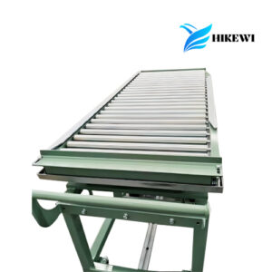
A roller bed conveyor is a material-handling system in which a series of rollers forms the supporting surface for transported products. Loads rest directly on these rollers and move either through gravity, manual force, or a powered drive system.
This configuration belongs to the broader category of a conveyor system, which is mechanical handling equipment designed to move materials between locations or production stages. Roller-based systems are particularly suitable for products with rigid and reasonably flat supporting surfaces because the load must bridge the spaces between adjacent rollers.
Typical conveyed items include cartons, containers, pallets, panels, fixtures, workpiece carriers, packaged products, and industrial assemblies. The important factor is not the product category itself but whether its underside can maintain stable contact with several rollers during movement.
The term “roller bed conveyor” can sometimes create confusion because “roller bed belt conveyor” is also used in conveyor engineering. In a roller bed belt conveyor, a continuous belt carries the product while rollers underneath the belt reduce sliding resistance. In the type discussed throughout this article, the product contacts the rollers directly.
Making this distinction early is important. Direct-contact roller conveyors and belt-over-roller conveyors use rollers for different mechanical purposes and therefore have different selection criteria.
A direct-contact roller bed conveyor transfers load through a simple but important structural path. Product weight passes into the rollers, then through the shafts and bearings into the conveyor side frames, support legs, mounting points, and finally the supporting structure beneath the system.
The rollers can rotate freely or receive mechanical power. In a gravity configuration, movement is created by manual force, product momentum, or a controlled incline. Powered configurations use a motorized mechanism to rotate selected rollers so products can move automatically at a controlled speed.
This basic difference affects more than movement. Gravity systems are relatively simple, while powered systems make it easier to coordinate conveyors with sensors, production machines, accumulation zones, transfer mechanisms, and automated processes.
The existing Laienka roller conveyor provides an example of a configurable industrial system. Its current published specifications include roller diameters of 50–150 mm, roller spacing of 80–300 mm, conveying speeds of 0.5–3 m/s, individual machine lengths of 1–10 m, and rated load capacities of 50–1000 kg/m.
These values should not be interpreted as universal roller bed conveyor standards. They illustrate why conveyor selection normally involves multiple parameters at the same time. The correct combination depends on the load being conveyed and the way the system will operate.
A reliable design comes from matching the conveyor to the load rather than maximizing individual specifications. Larger rollers, a stronger motor, or a heavier frame can be useful in the right situation, but none of these improvements can compensate for incorrect product support or unsuitable transfer geometry.
The following table summarizes the main factors that should be evaluated before finalizing a roller bed conveyor configuration.
| Design Factor | Why It Matters | Practical Evaluation |
|---|---|---|
| Product weight | Determines structural and drive requirements | Maximum operating weight including carrier or pallet |
| Product dimensions | Influences conveyor width and roller contact | Minimum and maximum length, width, and height |
| Bottom geometry | Determines whether rollers can support the product | Flat base, pallet runners, feet, openings, irregular surfaces |
| Roller spacing | Controls load stability and support continuity | Shortest supporting dimension and travel orientation |
| Roller diameter | Influences stiffness and load resistance | Load, conveyor width, shaft size, operating conditions |
| Roller material | Affects durability and product interaction | Strength, surface requirements, operating environment |
| Bearings and shafts | Transfer forces between rollers and frame | Load cycles, speed, alignment, contamination |
| Drive method | Determines movement and control capability | Gravity, powered, chain-driven, zoned operation |
| Conveyor speed | Influences throughput and dynamic loading | Process timing, stopping distance, transfer conditions |
| Frame structure | Maintains alignment under load | Width, support spacing, bracing, accumulated loads |
| Transfer points | Affect smooth movement between sections | Height, gap, alignment, direction and speed |
| Automation requirements | Determine control and sensing needs | Sensors, stops, PLC logic, accumulation, machine interfaces |
These factors are closely connected. Changing roller pitch may alter how many rollers carry the load, which can influence individual roller forces. Increasing conveying speed may affect stopping requirements. Changing pallet orientation may completely alter the contact pattern between the load and the conveyor.
A useful design process therefore evaluates the conveyor as one mechanical system rather than selecting each component independently.
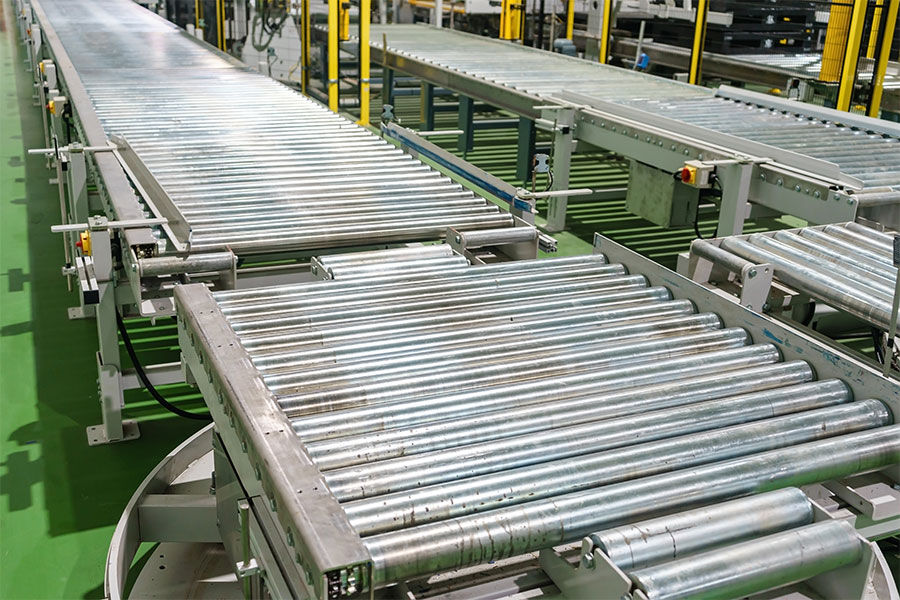
Roller spacing is one of the most important design considerations because the conveyor only works properly when the product maintains stable contact with the roller surface.
If the distance between rollers is too large relative to the product base, the load can rock, sag, strike the next roller, or become unstable. Small packages may even enter the gaps between rollers if their supporting length is inadequate.
A practical starting principle is to keep several rollers beneath the product during normal movement. For many rigid loads, maintaining support on at least three rollers provides a useful preliminary design reference, but this should not be treated as a universal engineering rule. Heavy, flexible, unusually shaped, or concentrated loads require more detailed evaluation.
Pallet construction makes this especially important. A pallet may have continuous runners, multiple blocks, individual feet, or openings across its underside. The engineer needs to identify which parts actually contact the roller bed.
Travel direction can change the answer. A pallet traveling with long runners aligned correctly across the rollers may receive stable support, while rotating the same pallet can place openings or unsupported areas directly above the roller gaps.
Reducing roller spacing can improve support, but using the smallest possible pitch is not automatically better. Additional rollers increase the number of bearings, shafts, sprockets, drive connections, and maintenance points. The objective is sufficient support with appropriate mechanical simplicity.
One of the most common mistakes in roller bed conveyor selection is asking only, “How much weight can the conveyor carry?”
Total weight matters, but the way that weight reaches the rollers can be just as important.
Imagine two loads with identical total mass. One rests on a rigid base that distributes force across six rollers. The other contacts only three rollers because its supporting feet are widely spaced. The second configuration can place approximately twice the average force on each supporting roller before considering uneven load distribution or dynamic effects.
Even this simplified calculation does not represent everything that happens in operation. Products rarely distribute their weight perfectly. Pallet deformation, uneven loading, frame deflection, dimensional tolerances, or an off-center center of gravity can cause certain rollers to carry more load than others.
Dynamic operation adds another layer. Starting, stopping, accumulating, transferring between conveyors, or striking a positioning stop creates forces that are not present when the load remains stationary.
For that reason, a roller bed conveyor intended for repeated production cycles should be assessed according to its complete operating condition rather than a static capacity figure alone.
The question is not simply whether the conveyor can support the product. It is whether the rollers, shafts, bearings, frame, drive system, and transfer points can handle the product repeatedly throughout its working cycle.
Roller diameter affects stiffness, rotational behavior, load resistance, and the available space for bearings and shafts. As conveyor width or product load increases, resistance to roller deflection becomes increasingly important.
However, roller diameter should never be evaluated by itself. A large-diameter tube connected to an undersized shaft can still experience unacceptable movement. Similarly, a strong shaft installed with unsuitable bearings can transfer excessive force into another weak point.
The bearing system must accommodate the expected radial loading, rotational speed, duty cycle, environmental conditions, and alignment. Reliable bearing operation also depends on proper installation. A technically adequate bearing can still experience shortened service life when shafts or frames are misaligned.
Roller construction therefore needs to be viewed as an assembly consisting of the tube, shaft, bearings, end structure, surface treatment, and mounting arrangement.
This systems approach is particularly important for long conveyor widths. As the distance between side frames increases, roller deflection becomes more significant. Heavy loads concentrated near the middle of a long roller may require a different configuration from the same load distributed near its ends.
The choice between gravity and powered operation should be based on the required process rather than on the assumption that one configuration is universally better.
A gravity roller bed conveyor is useful when products can move through manual force or controlled inclination. With fewer powered components, it can provide a straightforward solution for short transfers, workstations, temporary accumulation, or areas where operators control product movement.
Heavy products require particular attention on inclined gravity sections because increasing product mass also increases the energy that must be controlled as the load moves downhill. Stops, braking mechanisms, slope, and operating procedures therefore need careful consideration.
Powered conveyors are more suitable when loads need consistent automatic movement. A powered roller bed conveyor can control speed, coordinate products with upstream or downstream machinery, maintain spacing, and reduce dependence on manual pushing.
Chain-driven configurations are often considered where higher torque or demanding unit-load movement is required. Mechanical power is transferred between rollers, creating positive movement across the conveyor section. Chain tension, sprocket alignment, lubrication requirements, guards, and maintenance access become important design considerations.
Motorized or independently controlled roller zones provide another approach for automated handling. Instead of running an entire conveyor continuously, individual sections can activate when a product enters the zone. This supports controlled accumulation and more flexible process synchronization.
The appropriate choice depends on product weight, required speed, conveyor length, accumulation needs, positioning accuracy, operating frequency, and integration requirements.
Although the terms sound similar, these two conveyor concepts should not be treated as interchangeable.
In a direct-contact roller bed conveyor, the product sits directly on the rollers. This design works especially well for rigid products that can maintain stable contact across the roller pitch. The spaces between rollers also make it possible to incorporate stops, lifts, transfers, sensors, and other mechanisms into the conveyor structure.
In a roller bed belt conveyor, the product sits on a continuous belt. Rollers underneath support the carrying belt and help reduce friction compared with a belt sliding continuously over a solid bed. The product therefore receives continuous surface support rather than contacting the rollers themselves.
This distinction affects product compatibility. Cartons, pallets, panels, and fixtures with stable bases often work well on direct rollers. Small products, flexible packages, bags, or items with irregular bases may perform better on a continuous conveying surface.
Neither construction is inherently better. The correct choice depends on how the product interacts with the conveying surface.
For SEO and equipment specification purposes, using precise terminology also matters. Someone searching for a “roller bed conveyor” may be researching either configuration, so technical content should explain whether the transported item contacts rollers directly or sits on a belt supported by rollers.
Roller bed conveyors are useful wherever rigid unit loads need predictable horizontal movement between operational stages.
Warehouse and logistics systems can use them to connect receiving, storage interfaces, sorting areas, packing stations, accumulation zones, and dispatch processes. Pallets and rigid cartons can move through fixed routes while conveyors maintain a consistent handling height.
Manufacturing lines use roller conveyors to move machine components, fixtures, fabricated assemblies, panels, workpiece carriers, and containers between production stages. In these applications, conveying is often closely linked with processing. A product may stop for inspection, machining, assembly, labeling, or robotic handling before continuing to the next station.
Packaging operations can use roller sections for cartons and containers with stable bases. Gravity zones may provide manual accumulation, while powered sections can synchronize products with packaging machinery.
Roller conveyors are also useful as interfaces between machines. The straight roller conveyor configuration on the Laienka site, for example, is designed around flat, hard-bottomed items such as cartons, pallets, and panels and can operate through gravity or external power.
The most suitable application is therefore defined by product geometry and process requirements rather than industry name alone.
The roller bed is only as reliable as the structure supporting it.
Side frames must maintain the roller positions under operational loading. If the frame deflects excessively, the rollers may no longer remain parallel or level. This can cause products to drift, create uneven bearing loads, interfere with drive components, or increase resistance.
Support-leg spacing must also account for the real loading pattern. A long conveyor carrying several accumulated pallets may experience substantially different structural forces from a conveyor transporting one product at a time.
Transfer areas often require additional consideration. Product stops, lifting units, directional transfers, robots, and other mechanisms can introduce concentrated forces into the frame. Reinforcement may therefore be required around these areas rather than distributing frame strength uniformly.
Installation is equally important. A correctly designed frame installed on an uneven support surface can still produce poor roller alignment. Sections should be leveled and aligned so loads move smoothly across conveyor joints.
This becomes even more important when several conveyors form one production line. Small height differences between sections can create repeated impact every time a product crosses a transition.
A roller bed conveyor does not operate in isolation. Loads usually enter from another machine, conveyor, palletizing station, workstation, or handling device and eventually leave for another process.
Transfer geometry therefore deserves as much attention as the main conveyor bed.
The gap between sections must be compatible with the bottom of the conveyed product. If the gap is too large, the leading edge of a container or pallet runner may drop before reaching the next roller. This produces impact, vibration, and potentially unstable movement.
Height alignment is equally important. Even a relatively small step between two conveyor sections can become significant when a heavy load repeatedly strikes it during production.
Speed should also be coordinated. A fast upstream conveyor transferring products onto a slower downstream section may create compression or impact. The opposite arrangement can produce excessive gaps between products.
Directional transfers create another challenge because product support changes during the movement. Chain transfers, pop-up devices, turntables, lifts, and other mechanisms need sufficient capacity and appropriate timing to support the load while it leaves one conveyor and engages with another.
A smooth transfer is therefore the result of matching mechanical geometry, product support, and control logic.
Modern roller bed conveyors increasingly operate as components within automated manufacturing and material-handling systems rather than as independent machines.
Sensors can detect product arrival, confirm occupancy, control accumulation, identify positioning errors, and communicate with upstream and downstream equipment. A control system can then determine when each conveyor zone should start, stop, accelerate, or release a load.
This approach becomes valuable when products must interact with robots, palletizers, inspection equipment, production machines, lifting units, storage systems, or automated transfer stations.
Mechanical stability still comes first. Control software cannot permanently compensate for incorrect roller spacing, unstable product support, excessive frame deflection, or a poorly designed transfer gap.
For precise positioning applications, the conveyor may move at normal speed through most of a section and slow before reaching the final stop. This reduces impact while improving repeatability. Where products accumulate, individual zones can release loads only when downstream space becomes available.
When automation is expected, planning sensor locations, cable routes, control panels, stops, guards, and maintenance access during the original mechanical design is usually more effective than adding them after the conveyor is installed.
Routine inspection helps maintain predictable conveyor operation and can reveal small problems before they influence surrounding components.
Rollers should rotate freely and remain aligned. Abnormal noise, resistance, visible deformation, looseness, or surface damage can indicate developing problems. A seized or damaged roller increases resistance and may shift additional load onto neighboring rollers.
Bearings should be monitored according to operating conditions and component design. Contamination, misalignment, repeated shock loading, and unsuitable lubrication practices can all influence bearing performance.
Powered systems require additional attention to chains, belts, sprockets, motors, couplings, and tensioning mechanisms. Excessive drive tension can increase bearing forces, while insufficient tension may introduce shock, slip, or inconsistent movement.
Frame fasteners and conveyor supports should also be checked periodically. Repeated loading can reveal looseness or alignment changes that were not obvious during installation.
Cleaning requirements depend on the application environment. Dust, chips, packaging fragments, process residue, and other contaminants can accumulate around rollers or drive components. Good conveyor design should therefore provide reasonable access to areas that require inspection or cleaning.
Maintenance should not be considered separately from conveyor selection. Equipment that is difficult to inspect or service can create unnecessary downtime even when its original mechanical design is technically sound.
Selection should begin by documenting exactly what will travel on the conveyor. Record the minimum and maximum product dimensions, total operating weight, bottom structure, orientation, center of gravity, and any pallet or fixture that moves with the product.
Next, determine how the load contacts the rollers. Identify the shortest supporting dimension and estimate how many rollers will remain beneath the product during movement. This provides a basis for evaluating roller spacing.
Then define the operating requirements. Conveyor length, usable width, speed, throughput, start-stop frequency, accumulation, working height, transfer points, movement direction, and positioning requirements should all be considered.
Drive selection follows from the process. Gravity may be appropriate for simple transfers, while powered or zone-controlled systems are better suited to automatic transport and synchronization.
The surrounding environment also matters. Dust, moisture, process debris, cleaning requirements, temperature, operating hours, noise expectations, and maintenance access can influence roller, bearing, frame, and drive selection.
Finally, consider how the conveyor will connect with other equipment. A technically suitable roller section can still perform poorly if machine interfaces, transfer heights, product orientation, or control signals are not coordinated.
A good conveyor specification therefore describes the entire handling task rather than simply requesting a particular roller diameter or load rating.

Choosing roller pitch without examining the product underside is one of the most frequent design mistakes. External product dimensions alone do not reveal whether pallet runners or container supports will remain in contact with enough rollers.
Another mistake is treating total payload as the only load-capacity requirement. Concentrated loading and uneven weight distribution can place much greater forces on individual rollers than a simple average calculation suggests.
Selecting the drive before defining the required movement can also lead to unnecessary complexity or inadequate control. The drive should respond to process needs such as speed, positioning, accumulation, throughput, and automatic coordination.
Transfer points are often underestimated because attention is concentrated on the main conveyor length. In practice, transitions are some of the areas where impact, instability, and load concentration are most likely to appear.
Overlooking future automation can create similar limitations. Even when a conveyor initially operates manually, allowing suitable space for sensors, stops, control equipment, transfer modules, and cable routing can make future integration easier.
The most reliable roller bed conveyor is therefore not simply the system with the strongest components. It is the system in which product geometry, roller support, structural design, drive method, transfers, controls, and maintenance requirements all fit the same material-handling process.
A roller bed conveyor can provide a simple and reliable method for moving cartons, pallets, panels, carriers, components, and other rigid unit loads, but successful operation depends on careful application matching.
The selection process should begin with the product itself. Weight matters, but bottom geometry, dimensions, travel orientation, center of gravity, and contact with the rollers are equally important. These factors determine appropriate roller spacing, roller construction, frame design, and drive requirements.
The next step is to understand how the product will actually move through the process. Speed, accumulation, transfers, stopping, automation, and interaction with other machines can introduce forces and control requirements that are not obvious from static load capacity alone.
Treating the conveyor as a complete handling system produces a more useful engineering result than selecting rollers, frames, and drives independently. When every component is chosen around the same load and operating cycle, the roller bed conveyor can provide predictable movement, easier automation integration, and more manageable long-term maintenance.
What is a roller bed conveyor?
A roller bed conveyor uses a series of rotating rollers as the direct supporting surface for products such as cartons, pallets, panels, containers, and work carriers. Loads can move through gravity or powered rollers, depending on the required speed, control, conveying distance, and production process.
What products are suitable for a roller bed conveyor?
Roller bed conveyors work best with products that have rigid, stable supporting surfaces capable of bridging the gaps between rollers. Cartons, pallets, panels, trays, fixtures, and containers are common examples. Flexible bags or very irregular bases may require a continuous conveying surface instead.
How do I choose the correct roller spacing?
Roller spacing should keep several rollers beneath the load throughout normal movement and transfers. Product length alone is not enough; the supporting base, pallet runners, openings, direction of travel, product weight, and roller capacity should all be evaluated before determining the final pitch.
What is the difference between a roller bed conveyor and a belt conveyor?
A direct roller bed conveyor supports the product on individual rollers, while a belt conveyor provides a continuous carrying surface. Rollers suit rigid, stable-bottom loads, while belts can handle smaller or irregular products that cannot bridge roller gaps. Final selection depends on product geometry and process needs.
Can a roller bed conveyor be integrated with automation?
Yes. Powered roller conveyors can work with sensors, PLC controls, accumulation zones, stops, transfer modules, robots, palletizers, and production machinery. Effective integration requires mechanical stability, suitable product support, accurate transfers, and control logic designed around the complete operating sequence.